Sunday, December 30, 2018

Cura zig zag inside shell

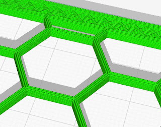
 Cura doing zig zag inside shell

The problem is that cura slicer wants to print zig zag pattern inside shell. The wall thickness is 1.2mm but for cura it is at an angle so i'd think that it doesnt recognize it as that. So it wants to do weird things inside of the wall.

So as to remedy that the easiest way i found was to change the wall line width to something smaller.

Tuesday, February 10, 2015

Before getting into multirotors

So your thinking about building a multirotor of your own? Good it's alot of fun, but requires a lot of research and some skills, as in you should have moved away from the protoboards and blinking led sketches. But don't be scared by that once you understand how all of the stuff in this field works then moving a step higher you can always rely on the steps you have been thorough already. With that i seriously suggest you to go find only the bare minimum in under 200 dollars euros, to get flying with your first quad. And i mean Quadcopter, because it really is the simplest. But don't count the transmitter in that price, that one is with you for the longhaul.

Quick suggestions what to get or have before getting anything multirotor related.

A good MULTIMETER that has instant continuity, volts, amps, diode function and good set of leads-crocodiles and sharp pointy ones (preferably sub 1mm or equivalent diameter).

Atmega programmer USBASP or equivalent will do, if your ready for some googling and failures.

Usb-FTDI adapter. You will not believe how much this will help you out in troubelshooting, firmware updates, etc. Preferably 3.3V variant.

Soldering iron, atleast 60w heating element, tips should be exchangeable, temperature-controllable. Most parts are made in the great land of China so be prepared to spend a few hours with troubleshooting with a multimeter and after that fixing some solderjoints so a small tip is a must. Also solder-wick, good solder (i have great experience with stannol brand), solder gel should be close-by.

A selection of wires in different sizes, pliers needlenose and regular. Selection of miniature screwdrivers flat, philips, torx and hex. Medium strength loctice threadsealant. Box cutter or exacto knife, drill with different types of small drillbits 2mm 2.5mm and so on. Tapping equipment in the same small measures. Most of the time you will meed M2 M3 M4 (sizes of bolt shafts) bolts, washers, nuts and grubscrews. M3 grubscrews i reccoment buying in bulk you will go through them in the bucketloads.

And as you can see we still haven't gotten to anything multirotor related yet. And in this break in your concentration i will try to apologize somewhat, because it looks like i am rambling quite a bit, but i wish that you will have a better start in the hobby than i have had. I sort of just went with mi vision of things, but it was totally unexpected to how complicated and how quick it will become at first.

Wednesday, February 4, 2015

Multirotors and Atmega

It came as a surprise to me that atmel processors are used in rc multicopters. There are purpose built boards for this kind of a hobby. There are mainly 3 different trees evolved in this scene

1st ardupilot (APM) a mega2560 based board, basically a arduino mega with barometric, acceleration and gyro sensors built in, as of 2.7 version boards lacking a magnetometer which is put in a GPS add on. Its regarded as a goto board for GPS functionality. It has a separate windows GUI mission planner. Board has special connectors builtin for connecting gps , power sensors speed sensors and almost everything else you can imagine to add to your flying apparatus. Its very easy to upgrade just go online in GUI and press a button. Downside is that its relatively expensive, bulky and fine tuning is a bit cumbersome. As of now it has evolved from 8bit Atmega controllers to 32bit St chipset, board is codenamed PixHawk or PIX for short.
2nd Multiwii. Basically its like a proprietary mega or 328 board. Everything applies except updating from mission planner. But for the price its a lot better. Coming from an arduino background you should go this route. You don't need to buy a multiwii board. A regular arduino will do. Go to eBay and acquire some sensors, Velcro tape or a glue gun and you're set. Code is open and developed on a daily basis. Also its much easier to add your own code to it. Code is all commented and easy to understand and modify.
3rd are proprietary 3rd party flight controllers for example-32bit CC3d, KK board series (latest 2,1), built-in types, where the board is a part of the frame. They arent that common but they have quite a following most of the time, for example there are some enthusiast who will bash whatever choice of FC(flightcontroller) you have as long as it isn't a KK board.

All of the ESC(Electronic speed controller)-s that i have come across have been controlled by Atmega8 series processors. They are used to make DC voltage into AC that controls the brushless motors on the multirotor. Atmega is used for getting the information from the FC and after that to control the RPM of the motor that it's connected to. All of the main calculations as to hoq fast every motor has to is done by the FC. ESC is just a dumb device that gets a signal and makes the propellers go zoom.

Today I disected a Ublox 6M Gps receiver, and it too had an Atmega chip as a supplementary communications platform.

Tuesday, March 11, 2014

Arduino 4x20 LCD and 2 inputs comparator

Staring a new build. So as to that I had an idea, that it can be helpful for everyone starting with code writing to try and manipulate this snippet. It's a simple code to operate a LCD and 2 inputs on A0 and A1. It compares the two with if and else. After the comparator it makes a readable output on the LCD. From here it's very simple to put the comparison into outputs of your own choosing.


//4x20 LCD, 2 sensors in A0 and A1 compare them and output to the LCD
// include the library code:
#include <LiquidCrystal.h>

// initialize the library liquidcrystal.h with the numbers of the interface pins
LiquidCrystal lcd(12, 11, 5, 4, 3, 2);

int sensorPin1 = A0; // defines input pin
int sensorValue1 = 0; // make a varianle sensorValue
int sensorPin2 = A1;
int sensorValue2 = 0;

void setup() {
  // set up the LCD's number of columns and rows: 
  lcd.begin(20, 4);

}

void loop() {

  sensorValue1 = analogRead(sensorPin1); // get the value of sensor 1
  sensorValue2 = analogRead(sensorPin2); // get valur for sensor 2

    lcd.setCursor(0, 0); // Set cursor to top left
  lcd.print(sensorValue1);

  lcd.setCursor(0, 1);
  lcd.print(sensorValue2);

  if (sensorValue1 < sensorValue2){
    lcd.setCursor(0, 2);
    lcd.print("1 is higher than 2");
  }
  else{
    lcd.setCursor(0, 3);
    lcd.print("2 is higher than 1");
  }

  delay(200);
  lcd.clear();


}

Sunday, February 2, 2014

Max7219 and a LED matrix with Arduino, blinking LED-s the hard way

DIY led matrix
DIY 7805 PSU
 First trial to make the 7219 work with Arduino. I had ordered the MAX7219-s a good few months ago, but still hadn't made anything with them. So this is mi stab at making them work. In mi junk bin i had a bunch of perf board and white led-s so just a matter of soldering together I thought. Well soldering is the easy part but to mi surprise it took a good hour or so to solder the 7805 coupled with 7219 and the led matrix together.

So mi first attempt. To replicate or try it for yourself you need.

  • Soldering iron
  • 30 LED-s
  • MAX7219 IC
  • 7805 Voltage regulator
  • 10 uF and 100 uF capacitors
  • jumper wires

Max7219 connected with DIY 5x6 Led matrix


Wednesday, January 22, 2014

Wireless 433mHz with Arduino, hitting the radiowaves

433mHz sender unit(left) and receiver unit (right)
I picked a pair of these up for 0.99$ each, so who can resist the tempation.

ACS712 30A interface with Arduino, measuring power usage

ACS712 30A sensor
The ACS712 is a hall-effect sensor, so when in using it be careful not to have any magnetic interference hitting the thing.There many variations of the IC this here is the 30A version. The current capabilities it can handle id conveniently located on the chip itself.